
- #HOMEBREW AMPLIFIER UPDATE#
- #HOMEBREW AMPLIFIER MANUAL#
- #HOMEBREW AMPLIFIER FULL#
- #HOMEBREW AMPLIFIER TV#
Kit building has always been a fun experience. I swapped the controls back to normal and began completing the amp.

This would not ordinarily be a problem but the treble pot is unique in the Bogen with a center tap that is grounded. I found that the bass and treble pots had been swapped. The parts for the first two tubes had been removed. With the exception of a couple of ceramic caps, all of the caps were replaced. Nearly all the capacitors were the color-striped Sprague "Black Beauty" types now often called "Black Uglies" because they are prone to DC leakage which can upset tube bias and damage tubes and transformers. The schematic was easy to find on the web. The first task was to locate tubes for the Bogen. As expected, the amp performed properly after the work.Ĭompleting and troubleshooting the Bogen DB-110 amp Cleaning the controls and tube pins with deoxit completed the update. I added a cap in the plate circuit of the magnetic cartridge preamp to keep B+ voltage off the input selector switch. I replaced the power cord with a safer three-wire grounded version and eliminated the now unnecessary cap from the AC power line to the chassis.

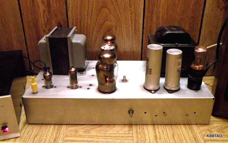
I replaced all the coupling capacitors and other caps that see high voltage in the homebrew amp but not the tone control caps as that was not needed.
#HOMEBREW AMPLIFIER UPDATE#
With a resurgence in interest in tube amps, I decided to update the homebrew Arkay clone and finish the Bogen.
#HOMEBREW AMPLIFIER FULL#
I acquired a better integrated full stereo tube amp shortly thereafter so both 6V6 amps were shelved. Therefore it remained as an unfinished project. I played with it for a bit but did not have a schematic. The Bogen DB-110 amp was a kit that had been modified and had nearly all the parts for the two preamp tubes removed. In high school, I traded a car radio for another amp that also had a push-pull pair of 6V6 output tubes. I moved the resistor and then enjoyed a properly working amp. It should go the first terminal (the left-most terminal on the pictorial). The pictorial incorrectly shows a 220K ohm resistor connected to the second terminal on the terminal strip. I traced the problem to an error in the pictorial. When completed, the amp worked somewhat but had a great deal of distortion. Had I known the output transformer was designed to handle 20 watts, I might have built the amp with a pair of 6L6 output tubes using a larger power transformer. I had a Stancor A-3830 universal output transformer that was too large for mounting under the chassis so it was mounted on top.
#HOMEBREW AMPLIFIER MANUAL#
I also substituted a second 6SL7 for the 6SC7 since the tube manual showed both to be high mu dual triodes. The RCA tube handbook provided the information for the substitution.

I substituted a type 80 rectifier for the 5Y3. Like all homebrew builders, I substituted some parts based on what I had on hand. The Arkay A-12 uses a 6SC7 for two stages of preamp and a 6SL7 for preamp and directly coupled split-load phase inverter. Thanks go to Deane VE6BPO for not only helping to identify the amp as the Arkay A-12 but for locating and scanning the Radio-TV Experimenter article to PDF. Over the years I had forgotten that the amp was an Arkay. I also ordered a blank chassis, four knobs, a tube, and a few resistors and capacitors from the Lafayette Radio catalog.
#HOMEBREW AMPLIFIER TV#
Since I had stripped a few junk radios and TV sets, I had accumulated many of the needed parts. The set had push-pull 6V6GT output tubes and was rated at 10 Watts RMS output. The article showed construction of the Arkay A-12 Hi-Fi amplifier kit and was complete with schematic and under-chassis pictorial. Some years ago, as a teenager of 15, I decided to homebrew an audio amp I had seen in an article in a 1958 Radio-TV Experimenter magazine. 6V6 Audio Amp parade A tale of three 6V6 Audio Amps


 0 kommentar(er)
