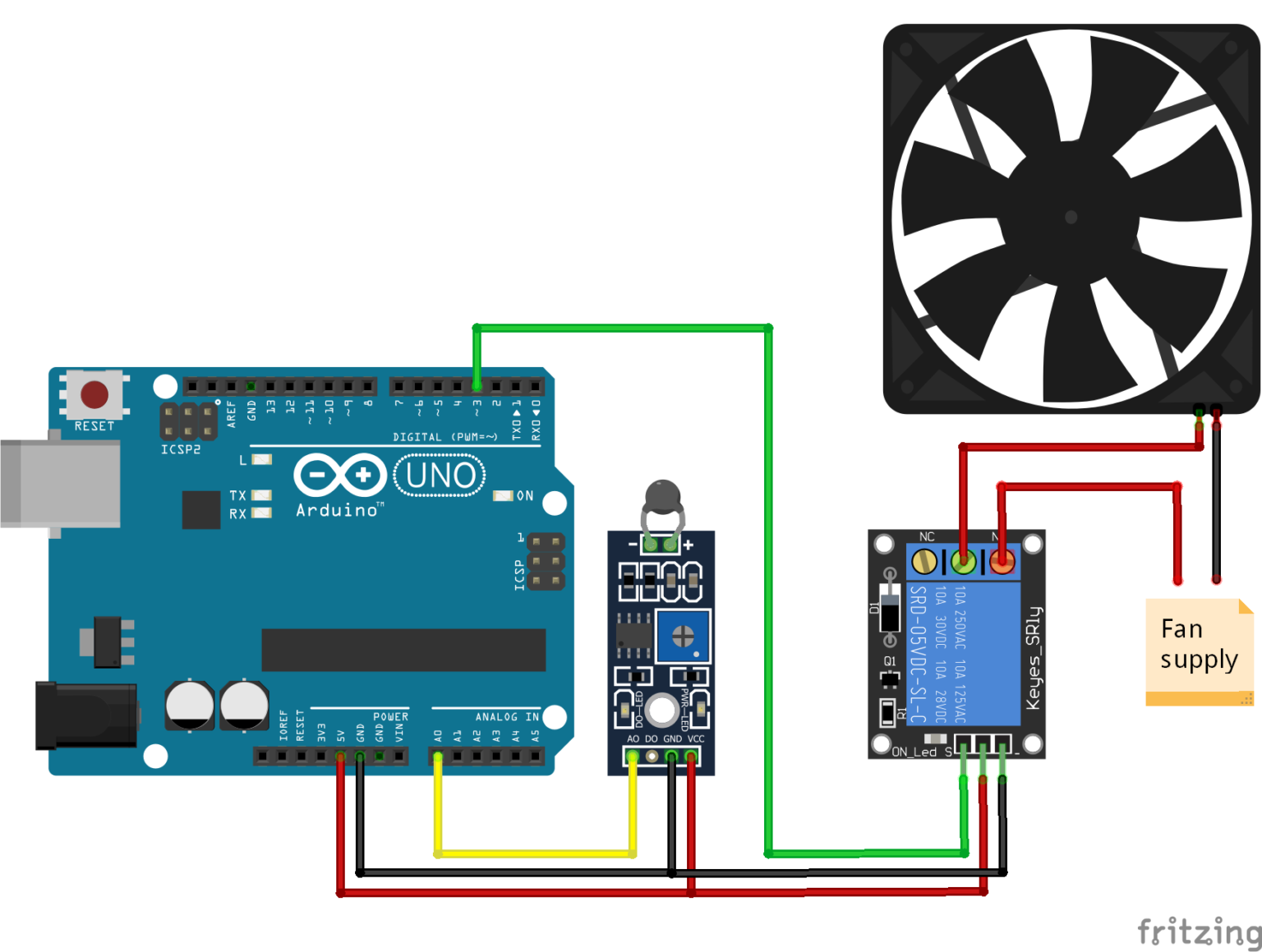
- #TEMPERATURE CONTROLLED FAN ARDUINO SERIAL#
- #TEMPERATURE CONTROLLED FAN ARDUINO CODE#
- #TEMPERATURE CONTROLLED FAN ARDUINO PC#
Lcd. Lcd.print(temp) // display the temperature If(temp = tempMin) & (temp tempMax) // if temp is higher than tempMax Int tempMax = 60 // the maximum temperature when fan is at 100% Int tempMin = 30 // the temperature to start the fan 0% Int tempPin = A0 // the output pin of LM35 LiquidCrystal_I2C lcd (0x3F, 16,2) // if error get address from i2c scanner


#include unquote this for LCD display without I2c
#TEMPERATURE CONTROLLED FAN ARDUINO CODE#
Copy and paste the below code in Arduino IDE, Select the correct COM port and Arduino as board and upload the code.
#TEMPERATURE CONTROLLED FAN ARDUINO PC#
Source code:Īfter connecting all the components according to the circuit diagram, next step is to upload the code to Arduino by connecting it to pc using an USB cable. A cheap and compact 2N2222 or BD139 NPN transistor is used in this circuit as it is efficient because it is used as a switch. The calculated percentage is sent to DC fan through the low frequency (PWM) pulse-width modulation signal which adjusts the fan speed by varying its Duty cycle. LM35 temperature sensor senses the temperature and send the analog signal to Arduino, then Arduino converts the analog signal to digital signal and display the value on LCD display and calculate the percentage of speed the fan should be spinned. Working of the temperature based fan speed controller Circuit When the temperature exceeds the max temp the 5mm LED light glows. The IN4007 Diode acts as a protection for the fan from being damaged. The 2N2222 NPN transistor acts as a controller switch which controls the speed of the fan by using the signal from the Arduino.

Use the power supply according to the fan power consumption and Arduino consumption. Interfacing LCD Display with Arduino in detailġ2V DC fan is connected to pin 11 of Arduino,Īrduino is powered from the 12V external power supply may be from an adapter or a battery to VIN and GND of Arduino.
#TEMPERATURE CONTROLLED FAN ARDUINO SERIAL#
If you want to connect the LCD display with out I2C refer the below article link. The default is arduino if the micro-controller communicates over a serial port, command otherwise. LM35 gives analog output voltage which is proportional to temperature and operates for a range of temperatures between -55 to 150 degree Celsius.Ī 16X2 I2c LCD display is connected to 5V and GND with Arduino 5V and GND and the I2c pins SDA and SCL of LCD module are connected to A4 and A5 respectively. Interface all the required components according to the circuit diagram shown below.įrom the above Schematic diagram you can see the LM35 temperature sensor Signal pin is connected to Arduino to A0 of Arduino and Vin and GND are connected to 5V and GND respectively. You can change the minimum and maximum temperature values in the code according to your requirement so the fan speed adjusts according to them. User can easily monitor the temperature values in Celsius and fan speed in percentage on the LCD display module connected with Arduino.


 0 kommentar(er)
